Signal Conditioning Controls
Note
The Signal Conditioning Controls window is available in ScanImage
The Signal Conditioning controls is helpful for a variety of uses, including:
Duplicating Displays on virtual channels
Setting a low pass filter on the PMT signal (medium speed vDAQ only)
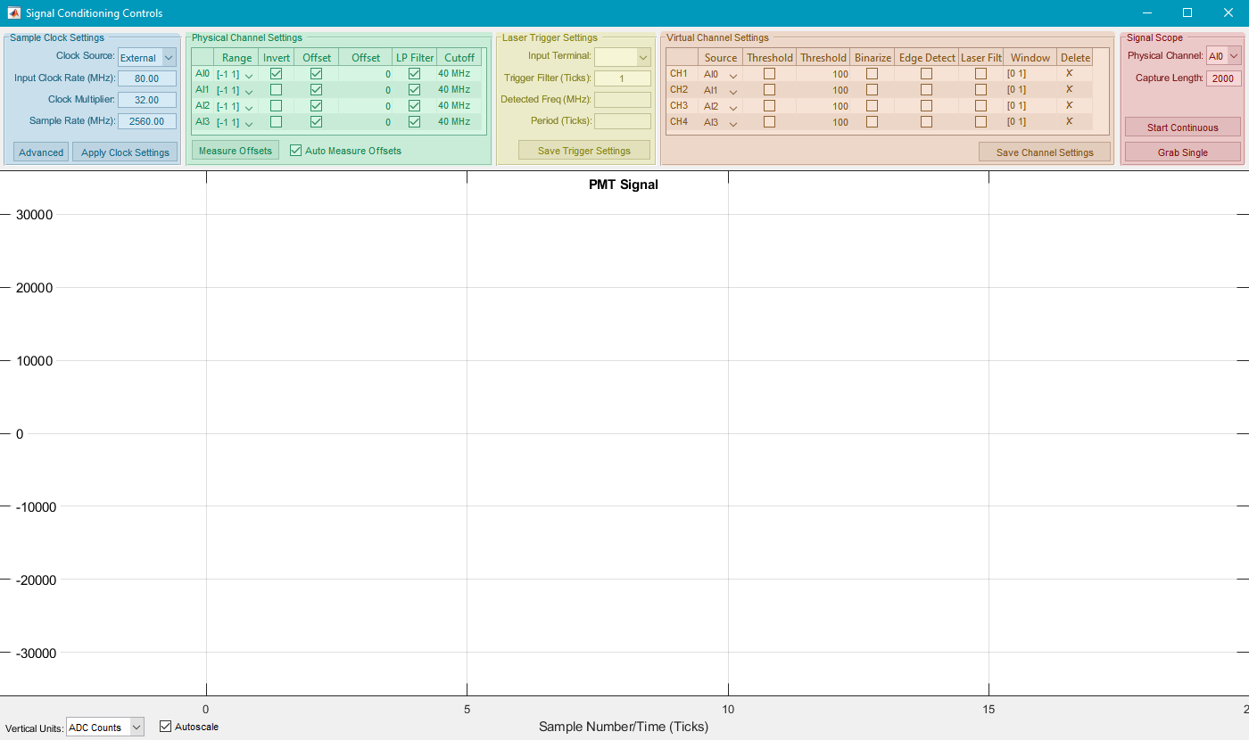
Sample Clock Settings (Blue)
Clock Source |
Select either the Internal Clock rate of 125MHz, or an external clock Note The high speed vDAQ using an external clock must receive a clock with a frequency 62.5 MHz - 84.375 MHz |
||||||
Input Clock rate |
The clock rate used to determine the Sample Rate. This is automatically detected. If the detected frequency is wrong for an externally supplied clock, then check the setup for time correlated photon counting |
||||||
Clock Multiplier |
This is essentially the number of samples collected for every rising edge of the Input Clock Rate (MHz) Note At present, the only supported clock multiplier for the high speed vDAQ is 32. |
||||||
Sample Rate (MHz) |
This is the Input Clock rate multiplied by the Sample Rate. Note ensure this is within the range of sampling rates supported by your DAQ.
|
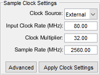
Physical Channel Settings (Green)
This essentially duplicates the role of the Channels window. As virtual channels are added, their settings can also be configured.
Tip
If using the medium speed vDAQ, you can specify the cutoff for a low pass filter in the right most column.
Physical Channel |
The channel for which the row’s settings should be applied |
Range |
The input voltage range that should be mapped to the ADC counts range of the DAQ |
Invert |
Whether higher ADC counts should be represented as brighter or darker pixels (checked inverts such that high counts are dark). |
Subtract Offset |
Whether or not to subtract the dark current offset. |
Offset Value |
The amount in ADC counts to subtract when subtract offset is enabled. |
LP Filter (medium speed vDAQ only) |
Whether or not to enable the anti-aliasing low pass filter |
Cutoff |
The cutoff frequency of the anti-aliasing low pass filter |
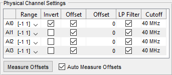
Laser Trigger Settings (Yellow)
Input Terminal |
The terminal from which the the laser trigger is received. For the HS vDAQ, this is only the CLK_IN (IN) port. On the MS vDAQ, this can be any DI or DIO port. |
Trigger Phase Adjust |
Compensate for any delay between the signal and triggering with this. You can adjust a maximum of the Clock Multiplier (samples per laser pulse) before looping. |
Detected Freq (MHz) |
This is a readout of the detected frequency. It will update after acquiring PMT samples from the Signal Scope panel (highlighted purple). |
Period (Ticks) |
This is number of times a sample is taken at the Detected Frequency (i.e. the Clock Multiplier, or the samples per laser pulse). Note This is relevant if synchronizing to an external sample clock. |
Virtual Channel Settings (Orange)
For the medium speed vDAQ:
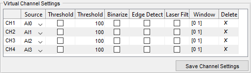
Channels |
ScanImage Display/Save Channels |
Source |
Analog Inputs assigned to a ScanImage Display/Save Channel |
Threshold (checkbox) |
Whether or not to apply the threshold specified in Threshold (editable text) |
Threshold (editable text) |
The quantity in ADC counts to compare the signal to to decide whether to write the pixel value to the image. Values less than the threshold are not written. |
Binarize |
If true, pixel values are written as either a 1 (above the threshold) or 0 (below the threshold) |
Laser Filter |
If true, the temporal window specified in the next column will be applied to mask which samples are binned for averaging |
Window |
the temporal window to mask which samples are binned for averaging |
Delete |
Can delete virtual channels by clicking the X |
For the high speed vDAQ:
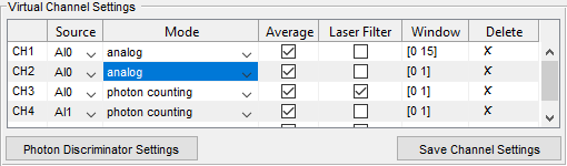
Channels |
ScanImage Display/Save Channels |
Source |
Analog Inputs assigned to virtual channel |
Mode |
Decide between analog (photo integration) or photon counting pipelines |
Average |
Whether or not to average (rather than add) samples before binning |
Laser Filter |
If true, the temporal window specified in the next column will be applied to mask which samples are binned for averaging |
Window |
the temporal window to mask which samples are binned for averaging |
Delete |
Can delete virtual channels by clicking the X |
Signal Scope (Red)
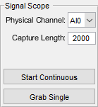
Physical Channel |
The port on the vDAQ PCIe card to sample from |
Capture Length |
The number of samples to collect |
Start Continuous |
Start monitoring samples on the PMT Signal graph |
Grab Single |
Grab a single capture length of samples and display on the PMT Signal graph. |