Waveform Generator
The waveform generator is a ScanImage device developed for use with the vDAQ which allows the use of an analog or digital output port to output predefined waveforms. ScanImage comes with several generic waveforms, but custom waveforms can be defined and used as well.
- Waveform generation can:
be triggered from a digital IO port
be continuously running or of finite execution length
If finite, can be configured as retriggerable to execute multiple times, or not retriggerable to execute just once.
- Waveform generation must:
Use exclusively analog output ports or digital output ports
Use sampling rates achievable by the vDAQ
Analog
Digital
2 MHz
20 MHz
Device Compatibility
The waveform generator can use any vDAQ analog output or digital output port that has not already been reserved by another resource/device.
Do not connect analog outputs or digital outputs to ports of low impedance. Analog outputs and digital outputs themselves are low impedance ports, so for example, do not “T” multiple digital outputs together. The maximum current sinking or sourcing for any one analog output port is 20 mA. Any given digital output can sink or source 16 mA.
Hardware Config
Connect analog outputs or digital outputs to device with input impedance suitable for the vDAQ. The maximum current sinking or sourcing for any one analog output port is 20 mA. Any given digital output can sink or source 16 mA.
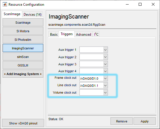
Waveform execution can be triggered by change of state of digital input or output ports. One can use any of the D2.X ports as a digital input to receive an externally generated trigger signal via BNC connection. Otherwise, to use a digital output port, one can configure a frame or beam modified line clock to be output on the same port that is configured for the waveform generator’s start trigger without requiring any additional BNC cable routing. One could even configure a waveform generator whose digital output is used as the start trigger of another waveform generator.
|
|
Software Config
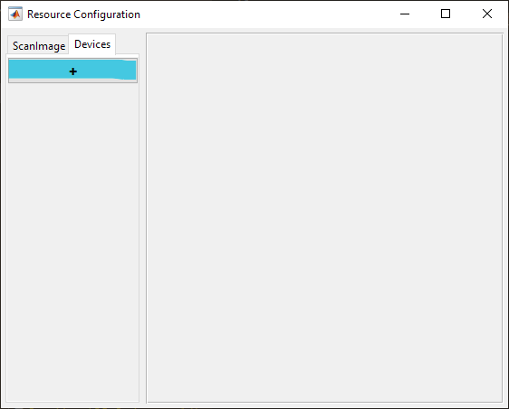
From the Resource Configuration window, under the Devices tab click the add device “+” button.
Select Miscellaneous from the sidebar and then Waveform Generator and click “Add”. Assign it a name and click OK.
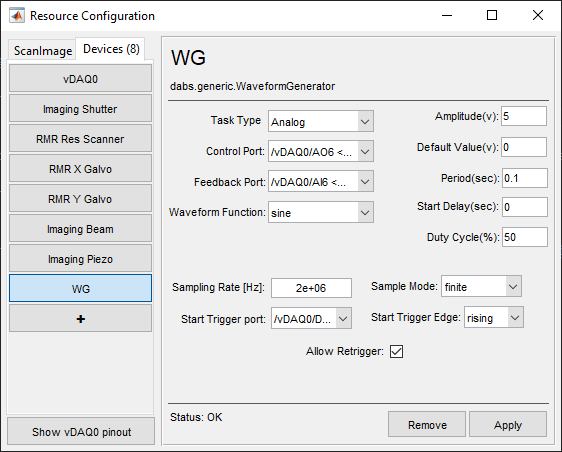
In the resource configuration page, configure the device according to your needs given the definitions provided below.
Definitions
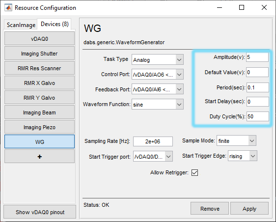
Main
Task Type |
Whether the waveform to be generated uses strictly TTL logic levels generated at digital outputs or analog voltage values at analog outputs |
Control Port |
Port used to output the signal |
Feedback Port |
Optional port used to receive a signal for waveform optimization Note Waveform optimization is a premium feature of ScanImage, and so cannot be used in Basic ScanImage. Only analog waveforms can utilize waveform optimization. |
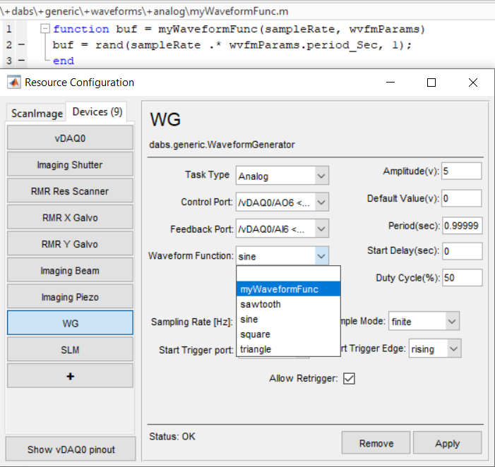
Waveform Function |
The waveform shape that will be output from the selected source Note The available waveforms for generation are those that are defined in package dabs.generic.waveforms.analog or dabs.generic.waveforms.digital as functions. Custom waveform buffer functions can be defined and saved within these packages and will automatically be used to populate this function dropdown. See below for information on creating a custom waveform buffer function. |
Amplitude |
The amplitude of the waveform to be generated in volts |
Default Value |
The voltage or logic level that should be applied whenever the task is in an idle/aborted state. |
Period |
The duration of time taken to execute the buffer in seconds. Note The execution time actually depends on the number of samples allocated to the waveform buffer and the sampling rate. To ensure the desired waveform period is used during execution, make sure the period is evenly divisible by the sample period (1 / sampling rate). |
*Start Delay |
Time in seconds that the signal will remain at default before wave generation. |
*Duty Cycle |
Percent of period that is to be set to a high state. |
Sampling Rate [Hz] |
The sampling rate of the task used to generate the waveform Note Set the sampling rate such that it is higher than the Nyquist frequency of the desired waveform you intend to generate and also is an integer multiple of the desired frequency (1 / Period). Failure to do so will result in waveforms that do not resemble the intended shape or do not execute at the desired frequency. |
Sample Mode |
Whether the task loops through the buffer continuously, or pauses/stops execution between consecutive start triggers. |
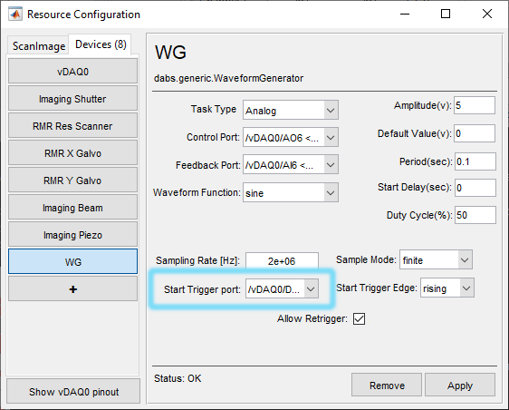
Start Trigger port |
(Optional) Which digital input or output port should be used to trigger output. If left empty, tasks will be started via software trigger when the start button is clicked from the waveform generator widget. |
Start Trigger Edge |
(Optional) If a start trigger port has been configured, this sets whether the task will be started on a rising or falling edge on the start trigger port. Note If a edge occurs during the execution of the sample buffer, then the edge will be ignored. |
Allow Retrigger |
Whether or not the task should stop after the first execution of the specified number of samples per trigger. |
Note
*Use of this parameter will need to be implemented in code by the user in the particular waveform that it will be used with
Defining Custom Waveforms
Waveforms are defined as functions that take the sample rate and a waveformParams object as input arguments and output the waveform as a vector of real numeric (analog) or logical (digital) data. See below for an example:
analog
function buf = sine(sampleRate, wvfmParams)
    amplitude = wvfmParams.amplitude_Volts;
    numSamples = sampleRate*wvfmParams.period_Sec;
    theta = linspace(0,2*pi,numSamples);
    buf= amplitude*sin(theta);
end
digital
function squareWave = square(sampleRate, wvfmParams)
    numSamples = sampleRate*wvfmParams.period_Sec;
    squareWave_ = zeros(floor(numSamples/2),1);
    squareWave_ = vertcat(squareWave_, ones(ceil(numSamples/2),1));

    squareWave = wvfmParams.amplitude_Volts*squareWave_;
end
Functions can be saved to either source code directory listed below depending on the intended task type.
\+dabs\+generic\+waveforms\+digital
\+dabs\+generic\+waveforms\+analog
Any new function files located in this directory will populate the waveform function dropdown menu in the waveform generator’s resource page after it is reloaded.
Waveform Parameters
The waveformParams object is defined in [source directory]+dabs+generic+waveformswaveformParams.m. The properties of the waveforms that it determines are as follows:
period_Sec |
Time in seconds between key points in waveform |
amplitude_Volts |
Amplitude of the waveform in volts. For digital waveforms this will be logic high for any value > 0 |
restVal_Volts |
% Resting value of the control line or waveform. |
dutyCycle |
Expressed as decimal representation |
startDelay_Sec |
Time in seconds that the signal will remain at default before wave generation |
To access and change the instance of waveformParams used with the waveformGenerator, go to the resource configuration page.
For the supplied waveforms, many of these parameters go unused. The user can edit or create new waveform functions that can make use of any of the parameters.
Waveform Optimization
If:
The user is running ScanImage Premium
The user has a device that uses analog signals which cannot be appropriately controlled through an existing ScanImage device driver,
this device provides an analog signal which has a monotonically rising or falling relationship with the output metric of interest (like position in microns for a fastZ device),
Then optimization can be used to force better similarity between the desired waveform and the calibrated feedback waveform. The underlying methods for the optimization are the same as for the galvo and fastZ Waveform Optimization. To use it, first click the Calibrate button from the waveform generator widget, and then click the Optimize button.